
Field Expedient Antennas
Half-Wave Dipole
Type: Center-fed, resonant half-wave wire antenna.
What it does: Provides single-band HF coverage with most radiation broadside to the wire.
How it works: The feedpoint divides the RF current between two equal quarter-wave legs. Current is highest near the center and voltage is highest near the wire ends.
Materials
- Two wire legs, 14 to 18 AWG stranded insulated wire, each cut slightly long at 234 / f MHz feet
- Center insulator or dipole center with SO-239
- Two end insulators
- 25 to 100 ft RG-8X or RG-58 coax with PL-259 as required
- 1:1 current choke or 6 to 8 coax turns on a 4 to 6 inch form at the feedpoint
- 550 cord or similar support rope, 25 to 50 ft
- Knife, multitool, tape, spare wire, throw line
Construction steps
- Determine target frequency and calculate total length with 468 / f MHz.
- Cut two equal legs slightly long, usually 2 to 4 percent extra for trimming.
- Strip the feedpoint ends and attach one leg to each side of the center insulator.
- Connect coax center conductor to one leg and shield to the other, or use the built-in socket on a dipole center.
- Add a choke at the feedpoint to keep RF off the outer braid.
- Attach end insulators and support rope.
- Raise the antenna as a flat top, keep both legs roughly straight and level, and keep the ends out of reach.
- Check SWR at the intended frequency and trim both legs equally in small increments.
Diagram
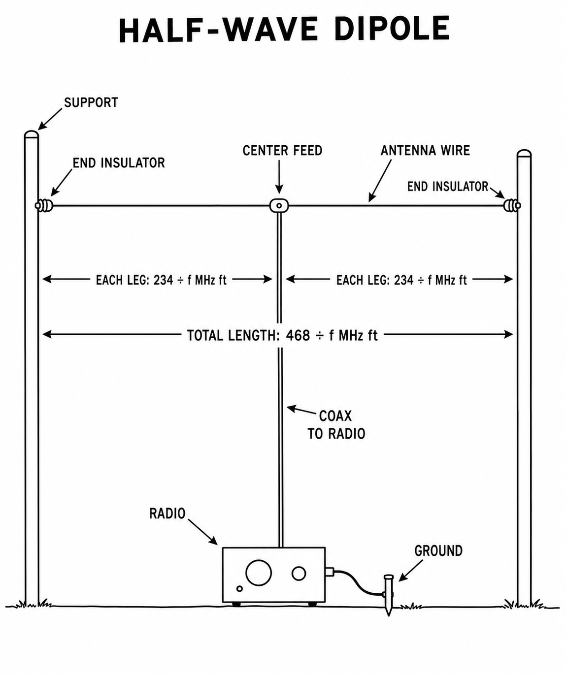
Text description: The diagram shows a horizontal wire suspended between two end supports. At the exact center is the feedpoint, where the coax drops down to the radio. Each leg from the feedpoint to an end support is cut to 234 divided by frequency-in-MHz feet, giving a total length of 468 divided by frequency-in-MHz feet. Example: for 7.1 MHz each leg is about 33 feet and the whole antenna about 66 feet.
Inverted-V Dipole
Type: Center-fed half-wave dipole with both legs sloping down from the feedpoint.
What it does: Provides dipole coverage where only one high support is available.
How it works: It uses the same two quarter-wave legs as a flat dipole. Sloping the legs changes the feed impedance and broadens the horizontal pattern.
Materials
- Same wire and feed hardware as a half-wave dipole
- Single center support, 20 to 40 ft preferred
- Two end tie-off points
- Coax and 1:1 choke
Construction steps
- Cut the dipole using the same formulas as a flat dipole.
- Attach the center to the highest available support.
- Run each leg down at roughly equal angle, ideally 45 degrees from horizontal.
- Keep the included angle near 90 to 120 degrees. Avoid making it too narrow.
- Anchor the ends 6 ft or more above ground if possible.
- Check SWR and trim equally.
Diagram
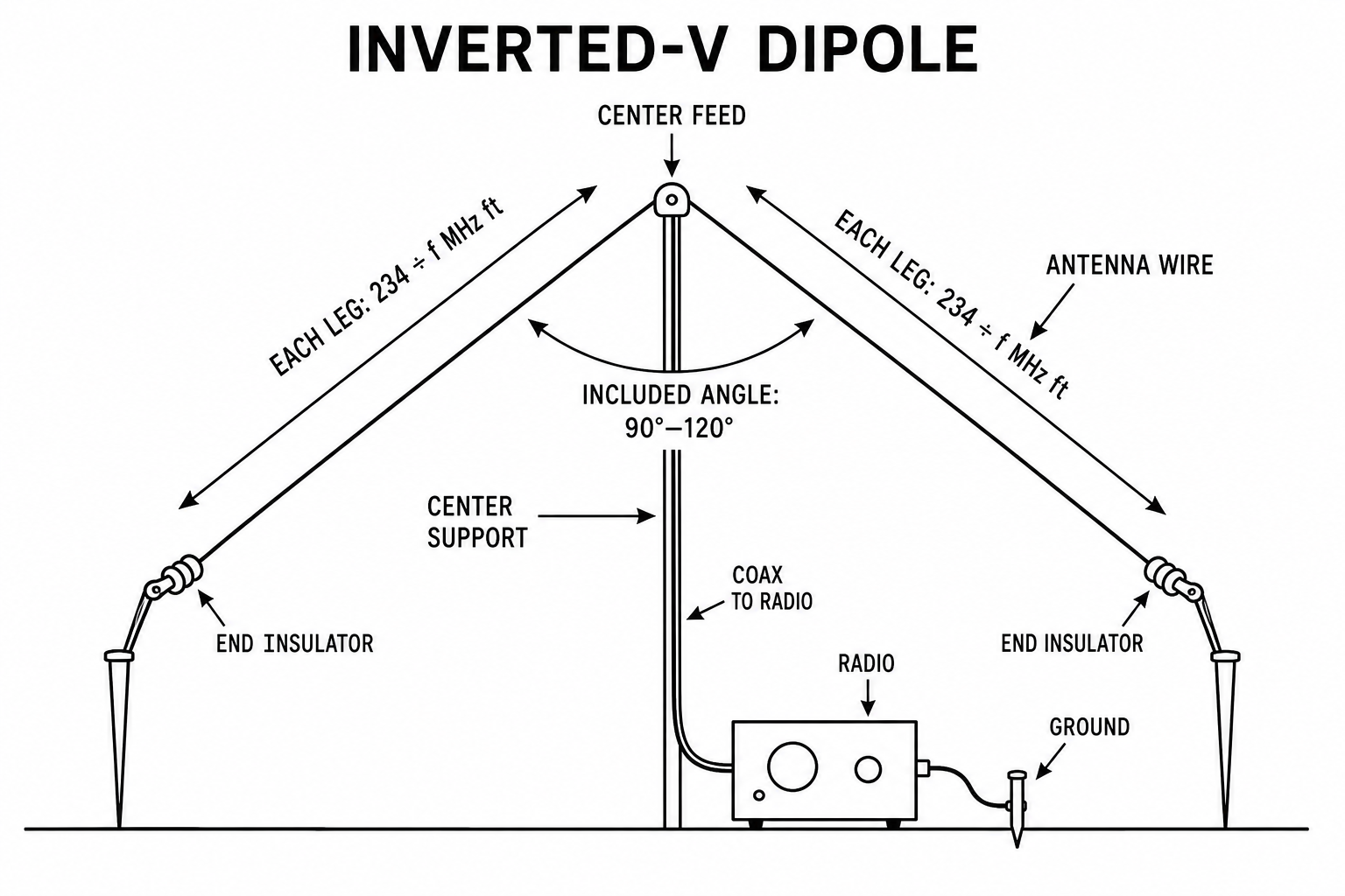
Text description: The diagram shows a single center support holding the feedpoint at the top, with two equal wire legs sloping down and outward to low anchor points, forming an upside-down V. The coax drops straight down from the apex. Each leg uses the same 234 divided by frequency-in-MHz feet cut as a flat dipole. The angle between the two legs should stay broad — roughly 90 to 120 degrees — and the wire ends must stay clear of people and the ground because voltage peaks there.
Quarter-Wave Vertical
Type: Base-fed quarter-wave vertical using radials as the return path.
What it does: Provides vertically polarized coverage in all horizontal directions.
How it works: The upright element forms one side of the antenna and the radials form the other. The coax center feeds the radiator while the shield connects to the radial system.
Materials
- Radiator wire or telescoping mast, 14 to 18 AWG wire or lightweight metal element, length 234 / f MHz feet
- Minimum 4 radials, preferably 8 to 16, each about quarter-wave long
- SO-239 mount, improvised feed plate, or terminal block
- 25 to 100 ft coax
- Ground stakes, tent pegs, tape, cordage
- Guys if the vertical is not self-supporting
Construction steps
- Cut the radiator to quarter-wave length.
- Cut at least four radials to the same quarter-wave length.
- Mount the radiator upright on an insulated base or support mast.
- Connect coax center conductor to the radiator.
- Connect coax shield to all radials.
- Spread radials evenly. They may slope down or lie on the ground.
- Guy the vertical if required and check for resonance.
- Trim the radiator, then fine-tune radial angle or length if needed.
Diagram
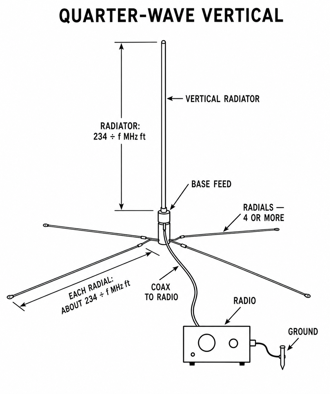
Text description: The diagram shows a single vertical wire or element rising from a feedpoint near the ground, cut to 234 divided by frequency-in-MHz feet. From the base, four or more radial wires of about the same length fan out along or just above the ground in all directions. The coax center conductor connects to the bottom of the vertical radiator, and the coax shield connects to all of the radials, which together act as the missing half of the antenna.
EFHW
Type: Resonant half-wave wire fed at one end through a high-ratio transformer.
What it does: Keeps the feedpoint near the operating position while the wire runs to one distant support.
How it works: A 49:1 transformer converts the high impedance at the end of the half-wave wire to a value the coax and radio can use. A counterpoise or controlled section of feedline provides the return path.
Materials
- 14 to 18 AWG insulated wire, approximately 468 / f MHz feet total for the fundamental band
- 49:1 transformer unit with binding post and coax connector
- Short counterpoise, often 0.05 to 0.1 wavelength, or use a common-mode choke on the coax
- Coax feedline, RG-8X common
- Support rope, end insulator
Construction steps
- Cut the radiator slightly long for the target half-wave band.
- Attach the wire to the high-impedance terminal of the transformer.
- Attach coax to the transformer output.
- Add a choke 10 to 20 ft down the coax if possible.
- Deploy the wire as a sloper, inverted-L, or horizontal run.
- If using a short counterpoise, attach it to the transformer ground terminal.
- Check resonance on the fundamental band and trim in small steps.
Diagram
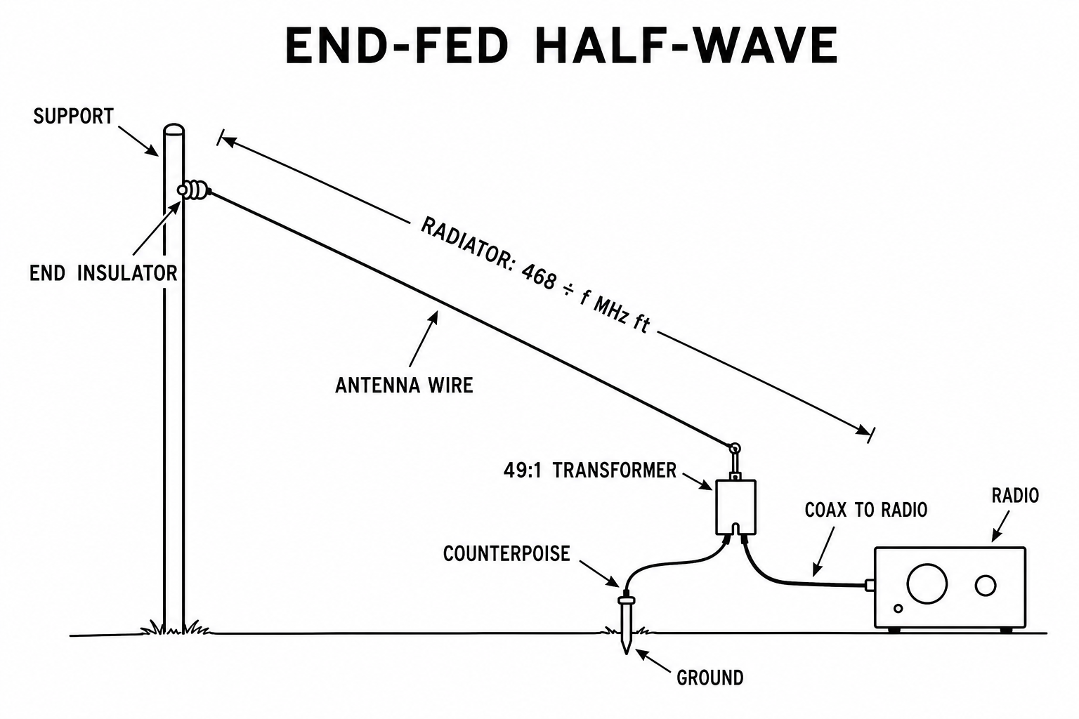
Text description: The diagram shows a single wire, 468 divided by frequency-in-MHz feet long, running from a matching transformer at one end up to a distant support at the other. Unlike a dipole there is no center feedpoint: the 49-to-1 transformer sits at the near end, with the coax dropping from it to the radio. A short counterpoise wire or a choke on the coax at the transformer gives the return currents somewhere to go instead of flowing back down the feedline.
Random Wire
Type: Non-resonant end-fed wire used with a 9:1 matching unit and a radio with a built-in tuner.
What it does: Provides multi-band operation when the available wire length and supports do not fit a resonant antenna.
How it works: The 9:1 matching unit reduces the impedance range presented to the radio. The radio's built-in tuner completes the match for each band and the counterpoise provides a defined return path.
Materials
- 14 to 20 AWG insulated wire, common field lengths 35 ft, 41 ft, 58 ft, 67 ft, 84 ft, 107 ft, 135 ft
- 9:1 unun with high-impedance wire post
- Counterpoise wire, 8 to 33 ft depending on band set
- Coax, short as practical if losses may be high
- Throw line, rope, insulator
Construction steps
- Select a wire length that avoids exact half-wave multiples on your main operating bands.
- Attach the long wire to the unun wire post.
- Attach a counterpoise to the unun ground side.
- Deploy the wire as high and clear as the site allows.
- Keep the first several feet of wire away from people and metal structures.
- Connect coax directly to the radio and use its built-in tuner carefully at low power first.
Diagram
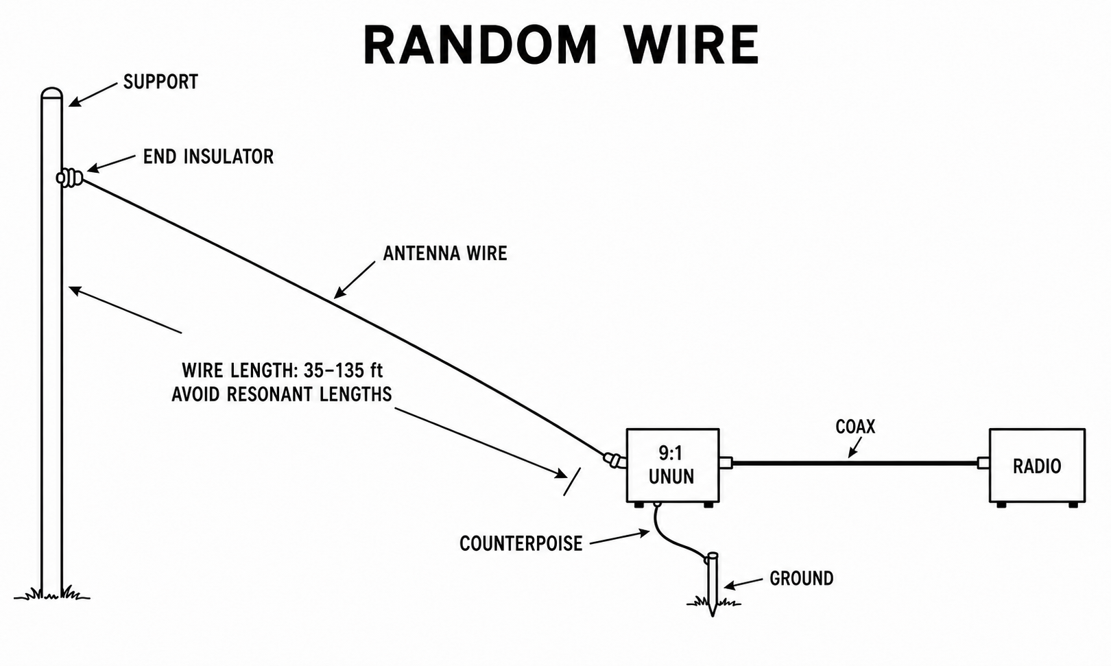
Text description: The diagram shows a long, non-resonant wire running from a 9-to-1 matching unit up to a support. The coax leaves the matching unit and runs directly to the radio, whose built-in tuner matches the antenna on each band. A counterpoise wire of 8 to 33 feet hangs from the ground side of the matching unit; the counterpoise or a ground connection is required for the match to be predictable.
NVIS
Type: Low-mounted horizontal dipole configured for Near Vertical Incidence Skywave operation.
What it does: Supports regional HF communications where low-angle propagation would skip over nearby stations.
How it works: Installing the horizontal wire well below a quarter wavelength favors high launch angles. The ionosphere returns that energy over the surrounding region.
Materials
- 40 m or 80 m dipole wire, 14 to 18 AWG
- Center insulator, end insulators, coax and choke
- Supports only 8 to 20 ft high, poles, brush, fence posts, vehicles, tree branches
Construction steps
- Build a standard dipole for 80 m, 60 m, or 40 m depending on the frequency plan.
- Install it low, usually 0.1 to 0.25 wavelength above ground.
- Keep the wire roughly horizontal. A slight sag is acceptable.
- Use a choke at the feedpoint.
- Check resonance and adjust length.
- Test with stations inside the target region, not just distant stations.
Diagram
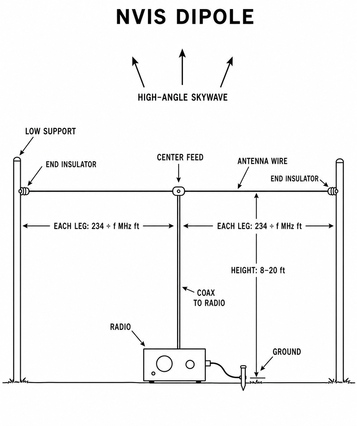
Text description: The diagram shows an ordinary center-fed dipole, but mounted deliberately low — only about 8 to 20 feet above ground on short supports. The coax drops from the center feedpoint just like a normal dipole. Because the wire is so close to the ground, most of its energy is launched nearly straight up, returns through the ionosphere, and comes back down over the surrounding region.
Long Wire
Type: End-fed wire at least a half wavelength long on the operating frequency.
What it does: Uses a long available path to produce coverage that becomes increasingly directional as the wire spans more wavelengths.
How it works: Current forms along the extended wire and creates multiple radiation lobes. A simple feedpoint connects the wire to coax, the radio's built-in tuner completes the match, and the counterpoise or ground provides the return path.
Materials
- 14 to 18 AWG wire, typically 1 to several wavelengths long on the intended band
- Feedpoint connector and a radio with a built-in tuner
- Counterpoise or ground
- Coax feedline and support hardware
Construction steps
- Select a route that points the wire generally toward the desired coverage area.
- Cut a wire at least a half-wave long, preferably longer if the site permits.
- Attach one end at the feedpoint.
- Run the wire in as straight a line as possible.
- Provide counterpoise or RF ground at the feedpoint.
- Use the radio's built-in tuner on the desired band and verify current draw and reported signal strength.
Diagram
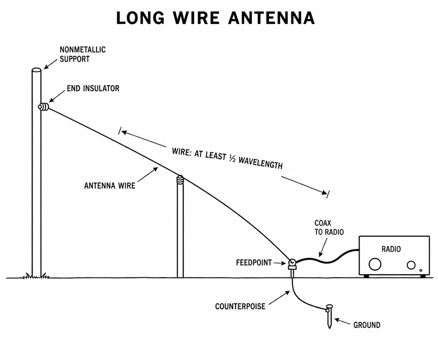
Text description: The diagram shows a feedpoint at the near end of a wire that runs away in one straight line, at least a half-wavelength and preferably several wavelengths long. The coax runs directly from the feedpoint to the radio, whose built-in tuner handles the match. A counterpoise or earth ground at the feedpoint provides the return path.
Inverted-L
Type: Base-fed wire with a vertical section and a horizontal top section.
What it does: Fits a longer radiator into a site that has one tall support but not enough height for a full vertical.
How it works: Current in the lower vertical section contributes vertically polarized radiation while the horizontal section completes the required wire length. Radials or a counterpoise form the return path.
Materials
- 14 to 18 AWG wire, total length based on target band, often quarter-wave to half-wave total
- Support mast or tree
- Radio with a built-in tuner
- Radials or counterpoise, minimum 2 to 4, more preferred
- Coax feedline
Construction steps
- Cut a wire for the desired total length.
- Raise the vertical section first using a mast or tree.
- Continue the remaining wire horizontally from the top support.
- Feed at the lower end through the base feedpoint.
- Lay out radials or a counterpoise.
- Use the radio's built-in tuner for lowest practical SWR.
Diagram
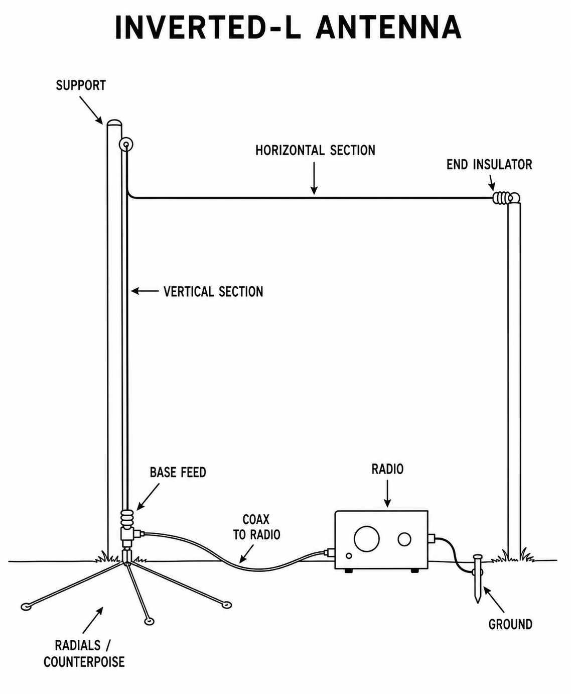
Text description: The diagram shows a wire shaped like an upside-down letter L: it rises vertically from the feedpoint, turns at the top support, and continues horizontally. The feedpoint is at the bottom of the vertical section, with coax running to the radio and several radial wires fanning out at the base.
Jungle Antenna / Sloper
Type: Sloping wire installed between one high support and a lower feed or anchor point.
What it does: Places a usable wire antenna above obstructed terrain when a level horizontal span is not available.
How it works: The slope is the physical layout; the selected wire length and the radio's built-in tuner determine whether it operates as an end-fed wire or a dipole section.
Materials
- 14 to 20 AWG wire cut to dipole leg, EFHW, or random-wire length depending on feed method
- Throw line and weight
- Insulator, cordage, tape
- Coax feedline to the radio; add a transformer only when the selected wire requires one
Construction steps
- Select the highest support available and a feedpoint that stays dry and accessible.
- Choose whether the antenna is a sloping end-fed wire or a sloping dipole leg system.
- Raise the far or high end first.
- Run the wire down at an angle, keeping it clear of trunks and wet foliage when possible.
- Connect coax directly to the radio and use its built-in tuner.
- Secure loose rope and mark the line to prevent walking into it.
Diagram
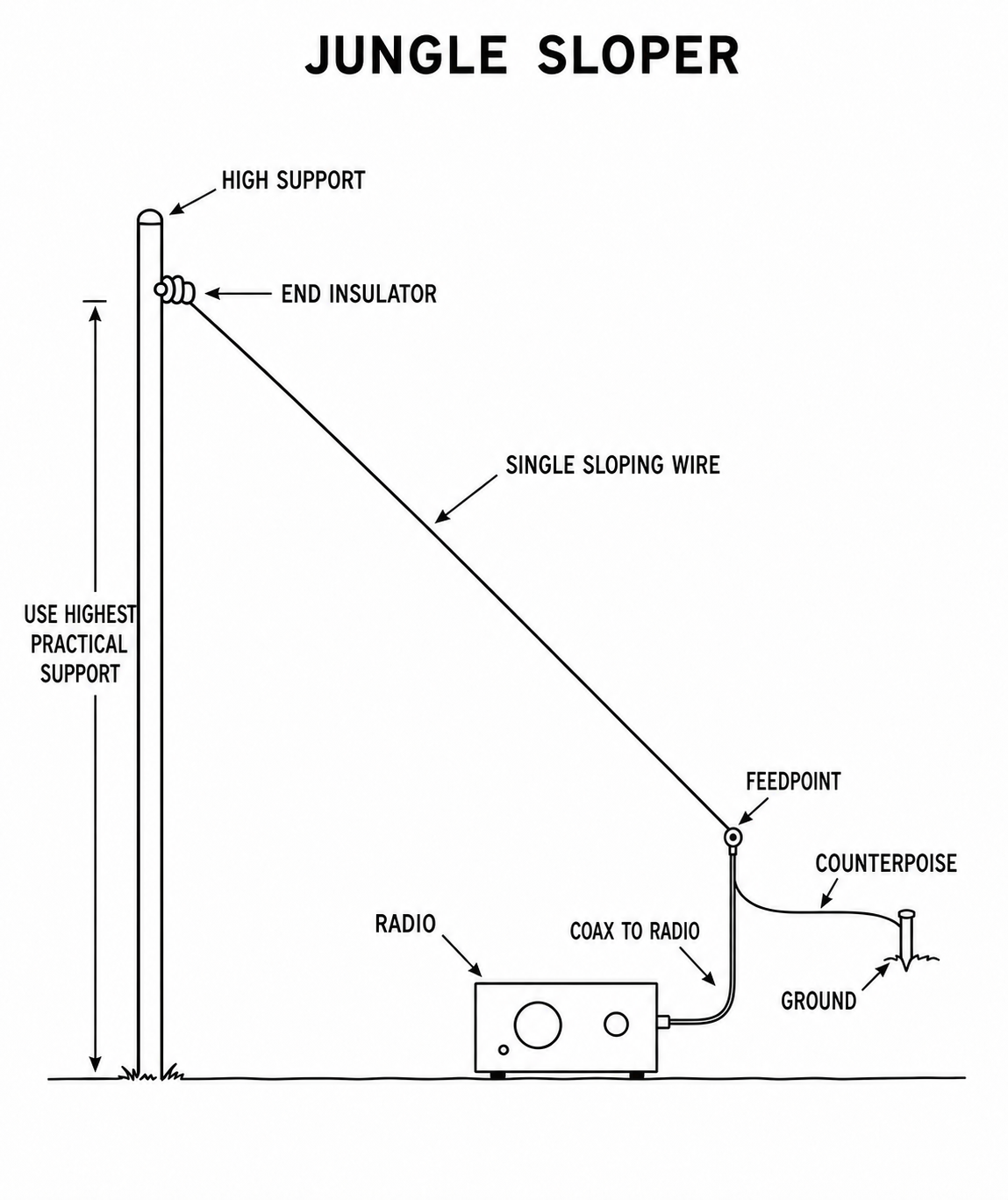
Text description: The diagram shows one high support holding the top end of a wire that slopes down to a feedpoint near the ground. The coax runs directly from that feedpoint to the radio, whose built-in tuner handles the match. The wire length is set by the selected feed method.